- Network Sites:
-
 EEPower Day is a free 1-day virtual conference. Learn More
The resistor is a passive electrical component that creates resistance in the flow of electric current. In almost all electrical networks and electronic circuits they can be found. The resistance is measured in ohms (Ω). An ohm is the resistance that occurs when a current of one ampere (A) passes through a resistor with a one volt (V) drop across its terminals. The current is proportional to the voltage across the terminal ends. This ratio is represented by Ohm’s law:
$$R = \frac{V}{I}$$
Resistors are used for many purposes. A few examples include limiting electric current, voltage division, heat generation, matching and loading circuits, gain control, and setting time constants. They are commercially available with resistance values over a range of more than nine orders of magnitude. They can be used as electric brakes to dissipate kinetic energy from trains, or be smaller than a square millimeter for electronics.
A resistor is a passive electrical component with the primary function to limit the flow of electric current.
The international IEC symbol is a rectangular shape with leads at each end as shown in the figure at left. In the USA, the ANSI standard is very common and represents a fixed resistor as a zigzag line (shown on the right).
|
IEC fixed resistor symbol |
ANSI fixed resistor symbol |
Resistors can be divided by functional type as well as resistance material. The following breakdown for the types can be made:
For each of these types, a standard symbol exists. Another breakdown based on the material and manufacturing process can be made:
The choice of material technology is specific to the resistor purpose. Often it is a trade-off between cost, precision, power, and other requirements. For example, carbon composition is a very old manufacturing technique that creates a low precision resistor, but is still used for specific applications where high energy pulses occur. Carbon composition resistors have a body made from a mixture of fine carbon particles and a non-conductive ceramic.
The carbon film technique creates resistors with a better tolerance (less resistance value variation) than carbon composition resistors. These are made of a non-conductive rod with a thin carbon film layer around it. This layer is treated with a spiral cut to increase and control the resistance value.
Metal and metal oxide film are widely used nowadays, and have better properties for stability and tolerance. Furthermore, they are less influenced by temperature variations. Like carbon film resistors, they are constructed with a resistive film around a cylindrical body. Metal oxide film is generally more durable.
Wirewound resistors are probably the oldest type and can be used for both high precision as well as high power applications. They are constructed by winding a special metal alloy wire, such as nickel chrome, around a non-conductive core. They are durable, accurate, and can have very low resistance value. A disadvantage is that they suffer from parasitic reactance at high frequencies.
For the highest requirements on precision and stability, metal foil resistors are used. They are constructed by cementing a special alloy cold rolled film onto a ceramic substrate.
Dependent on the application, the electrical engineer specifies different properties of the resistor. The primary purpose is to limit the flow of electrical current; therefore the key parameter is the resistance value. The manufacturing accuracy of this value is indicated with the resistor tolerance and is expressed as a percentage of the resistance value (for example ±5%). Many other parameters that affect the resistance value can be specified, such as long term stability or the temperature coefficient. The temperature coefficient, usually specified in high precision applications, is determined by the resistive material as well as the mechanical design.
In high frequency circuits, such as in radio electronics, the parasitic capacitance and inductance can lead to undesired effects. Foil resistors generally have a low parasitic reactance, while wirewound resistors are among the worst. For accurate applications such as audio amplifiers, the electric noise of the resistor must be as low as possible. This is often specified as microvolts noise per volt of applied voltage, for a 1 MHz bandwidth. For high power applications the power rating is important. This specifies the maximum operating power the component can handle without altering the properties or damage. The power rating is usually specified in free air at room temperature. Higher power ratings require a larger size and may even require heat sinks. Many other characteristics can play a role in the design specification. Examples are the maximum voltage or the pulse stability. In situations where high voltage surges could occur, this is an important characteristic.
Sometimes not only the electrical properties are important, but the designer also has to consider the mechanical robustness in harsh environments. Military standards sometimes offer guidance to define the mechanical strength or the failure rate.
Many standards exist for resistors. The standards describe ways to measure and quantify important properties. Other norms exist for the physical size and resistance values. Probably, the most well known standard is the color code marking for axial leaded resistors.
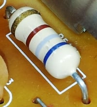
 Resistor with a resistance of 5600 ohm with 2 % tolerance, according to the marking code IEC 60062.
The resistance value and tolerance are indicated with several colored bands around the component body. This marking technique of electronic components was already developed in the 1920s. Printing technology was still not far developed, what made printed numerical codes too difficult on small components. Nowadays, the color code is still used for most axial resistors up to one watt. In the figure above, an example is shown with four color bands. In this example the two first bands determine the significant digits of the resistance value, the third band is the multiplying factor and the fourth band gives the tolerance. Each color represents a different number and can be looked up in a resistor color code chart or using a resistor color code calculator.
The color code can easily be decoded using this calculator.
In the 1950s, the increased production of resistors created the need for standardized resistance values. The range of resistance values is standardized with so called preferred values. The preferred values are defined in E-series. In an E-series, every value is a certain percentage higher than the previous. Various E-series exist for different tolerances.
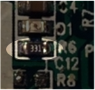 For SMD (Surface Mount Device) resistors, a numerical code is used, because the components are too small for color coding. SMD resistors are, just as for leaded resistors, primarily available in the preferred values. The size of the component (length and width) is standardized as well, and is referred to as resistor package. An example of an SMD resistor on a PCB is given in the picture. The marking “331" means that the resistance has a value of 33Ω x 101 = 330 Ω.
There is a huge variation in fields of applications for resistors; from precision components in digital electronics to measurement devices for physical quantities. A few popular uses are described below.
In electronic circuits, resistors are very often connected in series or in parallel. A circuit designer might, for example, combine several resistors with standard values (E-series) to reach a specific resistance value. For series connections, the current through each resistor is the same and the equivalent resistance is equal to the sum of the individual resistors. For parallel connections, the voltage across each resistor is the same. The inverse of the equivalent resistance is equal to the sum of the inverse values for all the parallel resistors. The articles resistors in parallel and resistors in series provide detailed introduction to these concepts and calculation examples. To solve even more complex networks, Kirchhoff’s circuit laws may be used.
Electrical current can be calculated by measuring the voltage drop over a precision resistor with a known resistance, which is connected in series with the circuit. The current is calculated by using Ohm’s law. This is a called an ammeter or shunt resistor. Usually this is a high precision manganin resistor with a low resistance value.
LED lights need a specific current to operate. A too low current will not light up the LED, while a too high current might burn out the device. Therefore, they are often connected in series with resistors to set the current. These are called ballast resistors and passively regulate the current in the circuit.
In cars, the air ventilation system is actuated by a fan that is driven by the blower motor. A special resistor is used to control the fan speed. This is called the blower motor resistor. Different designs are used. One design is a series of different size wirewound resistors for each fan speed. Another design incorporates a fully integrated circuit on a printed circuit board.

