- Network Sites:
-
 EEPower Day is a free 1-day virtual conference. Learn More
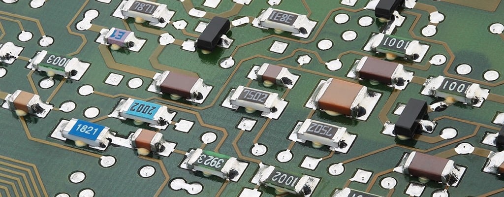 SMD resistors on a printed circuit board. Image used courtesy of TE Connectivity
SMD stands for Surface Mounted Device. An SMD is any electronic component that is made for use with SMT, or Surface Mount Technology. SMT was developed to meet the ongoing desire for printed circuit board (PCB) manufacturers to use smaller components and to be faster, more efficient, and cheaper when assembling components to the PCBs.
SMDs are smaller than their traditional through-hole counterparts. They are often square, rectangular or oval in shape, with very low profiles. Instead of wire leads that go through the PCB, SMDs have small leads or pins that are soldered to pads on the surface of the board. This eliminates the need for holes in the board and thereby allows both sides of the board to be more fully populated with components.
The manufacture of PCBs using SMT is similar to that for components with leads. Small pads of silver or gold plate or tin-lead are placed on the board for attaching the components. Solder paste, a mixture of flux and small balls of solder, is then applied to the mounting pads by a machine similar to a computer printer. Once the PCB is prepared, SMDs are placed on it using a pick-and-place machine. The components are fed to the machine in long tubes, on rolls of tape, or in trays. These pick-and-place machines can pick SMD device and place onto PCBs at rates of thousands of components per hour (cph); one manufacturer advertises a rate as high as 60,000 cph.
The board is then sent through a reflow soldering oven. In this oven, the board is slowly brought up to a temperature that will melt the solder. Once cooled, the board is cleaned to remove solder flux residue and stray solder particles. A visual inspection checks for missing or out-of-position parts and that the board is clean.
The term package refers to the size, shape and/or lead configuration of an electronic component. In SMD resistors, resistor package designators tell the length and width of the resistor. SMD packages may be given in inches as well as in millimeters. It is therefore important to check the manufacturer's documentation. The shape and size of surface mount resistors are standardized with most manufacturers use the JEDEC standards. The size of SMD resistors is indicated by a numerical code, such as 0603. This code describes the length and width of the package. More information is available in the discussion of Resistor Sizes and Packages.
Because of the small size of SMD resistors, there is often not room for the traditional color band code to be printed on them. Therefore, new resistor SMD codes were developed. The most commonly seen codes are the three and four digit system and an Electronic Industries Alliance (EIA) system called EIA-96.
In these systems, the first two or three digits indicate the numerical resistance value of the resistor and the last digit gives a multiplier. The number of the last digit indicates the power of ten by which to multiply the given resistor value. Here are some examples of values under this system.
Three digit system
Four digit system
The letter "R" is used to indicate the position of a decimal point for resistance values lower than 10 Ω. Thus, 0R5 would be 0.5 Ω and 0R01 would be 0.01 Ω.
Higher precision resistors, combined with the decreasing sizes of resistors, have created the need to have a new, more compact marking for SMD resistors. Therefore the EIA-96 marking system has been created. It is based on the E96-series, thus aimed at resistors with 1% tolerance.
In this system, the marking exists out of three digits: 2 numbers to indicate the resistor value and 1 letter for the multiplier. The two first numbers represent a code that indicates a resistance value with three significant digits. In the first table below, the resistance values for each code are given, which are basically the values from the E96 series. For example, the code 04 means 107 Ω, and 60 means 412 Ω. The second table below provides the multiplying factor for each letter code gives the final value of the resistor
Examples of converting EIA-96 markings to a resistance value:
The usage of a letter prevents the confusion with other marking systems. However, pay attention because the letter R is used in both systems. For resistors with tolerances other than 1%, different letter tables exist. As with package codes, these resistance value codes are common, but a manufacturer may use a variation on these or even something completely different. It is therefore always important to verify the manufacturer's marking system.
| Code | Value | Code | Value | Code | Value | Code | Value | Code | Value | Code | Value |
|---|---|---|---|---|---|---|---|---|---|---|---|
| 01 | 100 | 17 | 147 | 33 | 215 | 49 | 316 | 65 | 464 | 81 | 681 |
| 02 | 102 | 18 | 150 | 34 | 221 | 50 | 324 | 66 | 475 | 82 | 698 |
| 03 | 105 | 19 | 154 | 35 | 226 | 51 | 332 | 67 | 487 | 83 | 715 |
| 04 | 107 | 20 | 158 | 36 | 232 | 52 | 340 | 68 | 499 | 84 | 732 |
| 05 | 110 | 21 | 162 | 37 | 237 | 53 | 348 | 69 | 511 | 85 | 750 |
| 06 | 113 | 22 | 165 | 38 | 243 | 54 | 357 | 70 | 523 | 86 | 768 |
| 07 | 115 | 23 | 169 | 39 | 249 | 55 | 365 | 71 | 536 | 87 | 787 |
| 08 | 118 | 24 | 174 | 40 | 255 | 56 | 374 | 72 | 549 | 88 | 806 |
| 09 | 121 | 25 | 178 | 41 | 261 | 57 | 383 | 73 | 562 | 89 | 825 |
| 10 | 124 | 26 | 182 | 42 | 267 | 58 | 392 | 74 | 576 | 90 | 845 |
| 11 | 127 | 27 | 187 | 43 | 274 | 59 | 402 | 75 | 590 | 91 | 866 |
| 12 | 130 | 28 | 191 | 44 | 280 | 60 | 412 | 76 | 604 | 92 | 887 |
| 13 | 133 | 28 | 196 | 45 | 287 | 61 | 422 | 77 | 619 | 93 | 909 |
| 14 | 137 | 30 | 200 | 46 | 294 | 62 | 432 | 78 | 634 | 94 | 931 |
| 15 | 140 | 31 | 205 | 47 | 301 | 63 | 442 | 79 | 649 | 95 | 953 |
| 16 | 143 | 32 | 210 | 48 | 309 | 64 | 453 | 80 | 665 | 96 | 976 |
| Code | Multiplication Factor |
|---|---|
| Z | 0.001 |
| Y / R | 0.01 |
| X / S | 0.1 |
| A | 1 |
| B / H | 10 |
| C | 100 |
| D | 1000 |
| E | 10,000 |
| F | 100,000 |
Good to new learning
how could we differentiate, for example, `103` from 3-digit and EIA-93 color codes?