- Network Sites:
-
 EEPower Day is a free 1-day virtual conference. Learn More
 An LED (Light Emitting Diode) emits light when an electric current passes through it. The simplest circuit to power an LED is a voltage source with a resistor and an LED in series. Such a resistor is often called a ballast resistor. The ballast resistor is used to limit the current through the LED and to prevent excess current that can burn out the LED. If the voltage source is equal to the voltage drop of the LED, no resistor is required. LEDs are also available in an integrated package with the correct resistor for LED operation.
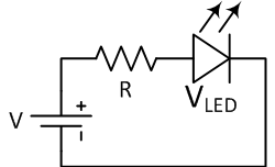
The resistance of the ballast resistor is easy to calculate using Ohm’s law and Kirchhoff’s circuit laws. The rated LED voltage is subtracted from the voltage source, and then divided by the desired LED operating current:
$$R = \frac{V - V_{LED}}{I}$$
Where V is the voltage source, VLED is the LED voltage, and I is the LED current. This way you can find the right resistor for proper LED operation.
This simple LED circuit with ballast resistor might be used as a power-on indicator for a DVD player or a computer monitor. Although this circuit is widely used in consumer electronics, it is not very efficient since the surplus energy from the voltage source is dissipated by the ballast resistor. Therefore, sometimes more complex circuits are applied to provide better energy efficiency.
In the following example an LED with a voltage of 2 V and an current of 30 mA must be connected to a 12 V supply.
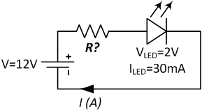
The ballast resistor can be calculated using the formula:
$$R = \frac{V - V_{LED}}{I} = \frac{12 - 2}{0.03} = 333 \Omega$$
The resistor must have a resistance of 333 Ω. If the precise value is not available, choose the next higher resistance value to keep the current below the LED limits.
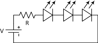
Often multiple LEDs are connected to a single voltage source with a series connection. In this way multiple resistors can share the same current. Because the current through all LEDs in series is equal, they should be of the same type. Note that lighting one LED in this circuit uses just as much power as multiple LEDs in series. The voltage source must provide a large enough voltage for the sum of voltage drops of the LEDs plus the resistor. Typically the voltage source is 50 percent higher than the sum of the LED voltages. Alternatively, a lower voltage source and a lower current can be used, by compensating for the lower brightness of each individual LED by using a larger number of LEDs. Furthermore, there is less thermal loss and the LEDs have a higher lifespan due to the lower load.
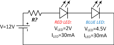
In this example two LEDs are connected in series. One red LED with a voltage of 2 V and a blue LED with 4.5 V. Both have a rated amperage of 30 mA. Kirchhoff’s circuit laws tell us that the sum of voltage drops across the circuit is zero. Therefore the resistor voltage must be equal to the voltage source minus the sum of the voltage drops of the LEDs. With Ohm’s law we calculate the resistance value of the ballast resistor:
$$R = \frac{V - V_{LED1} - V_{LED2}}{I} = \frac{12 - 2 - 4.5}{0.03} = 183.3 \Omega$$
The resistor must have a value of at least 183.3 Ω. Note that the voltage drop across the resistor is 5.5 V. It would have been possible to connect additional LEDs in the circuit.
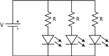
It is possible to connect LEDs in parallel, but it can create more problems than series circuits. The forward voltages of the LEDs must closely match, otherwise only the lowest voltage LED lights up and possibly burn out due to excess current. Even if the LEDs have the same specification, they can have poor matching of the I-V characteristics due to variations in the production process. This causes the LEDs to pass a different current. To minimize the difference in current, LEDs in parallel normally have a ballast resistor for each branch.
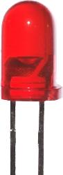
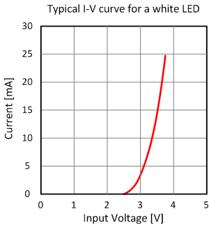 An LED (Light Emitting Diode) is a semiconductor device. It is essentially a P-N junction with a lead attached to each side. An ideal diode has zero resistance when forward biased and infinite resistance when reversed biased. In real diodes however, a small amount of voltage must be present across the diode to make it conduct. This voltage, along with other characteristics, is determined by the materials and construction of the diode. When the forward bias voltage becomes large enough, excess electrons from one side of the junction start to combine with holes from the other side. When this occurs, the electrons fall into a less energetic state and release energy. In LEDs this energy is released in the form of photons. The materials from which the LED is made determine the wavelength and, therefore, the color of the emitted light. The first LEDs were made with gallium arsenide and gave off a red light. Today LEDs are made from a variety of materials and can emit a range of colors. Voltages vary from about 1.6 V for red LEDs to about 4.4 V for ultraviolet ones. Knowing the correct voltage is important because applying too much voltage across the diode can cause more current than the LED can safely handle.
LEDs today are available in low and high power. LEDs typically give off less heat and use less power than an incandescent bulb of equal brightness. They also last longer than equivalent light bulbs. LEDs are used in a wide range of lighting and light sensing applications.
LEDs can be used as photodiodes. Photodiodes are semiconductors that behave in the opposite manner from LEDs. Whereas an LED will emit light as it conducts, a photodiode will generate current when exposed to the correct wavelength of light. An LED will exhibit this characteristic when exposed to light at a wavelength below its normal operational wavelength. This allows LEDs to be used in circuits like light sensors and fiber optic communication circuits.
I’m building a DIY electronic guitar. Instead of plucking strings attached to switches, I want to interrupt an infrared light beam, one for each “string”. Transmissive Optical Sensors look like a possibility—their LEDs and Detectors can be split / separated. So, what resistor do I need to power the 6 LEDs? I have a 3.3v or a 5V source available. I can’t tell from the TCST1103 Datasheet what the If or Voltage is for each LED. Also, should the 6 LEDs be powered in parallel or in series?
In the « Example of simple LED circuit » section, the current value in the text body shouldn’t be « 30 mili-amperes » instead of « 20 mili-amperes » ?