- Network Sites:
-
 EEPower Day is a free 1-day virtual conference. Learn More
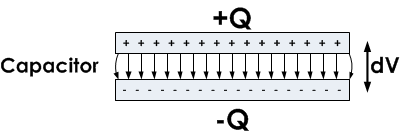 Capacitance is an ability of a body to store electrical energy in the form of electrical charge (Q). Practical resistors always exhibit capacitance as a parasitic property. Depending on the application, resistor capacitance might be easily disregarded, especially in DC circuits. In some applications, such as snubber resistors, the capacitive parasitic effect is actually a desirable effect. On the other hand, parasitic resistor capacitance can be a significant factor in high-frequency AC applications, creating an unwanted effect. The reason for this is that the impedance of a resistor with a parasitic parallel capacitance will decrease as the applied frequency increases. The higher the frequency, the lower the impedance is, which means that the resistor can no longer be observed as a constant element at high frequencies, and becomes a frequency-dependent element.
Electrical loads can be divided into two types: real (or resistive) loads and reactive loads. Real loads are used to convert electrical power into heat. An ideal resistor is a purely resistive load, which means that all the electrical power applied to the resistor is dissipated as heat. On the other hand, reactive loads convert electrical power into a magnetic or electric field and temporarily store it before returning it to the rest of the circuit. Reactive loads can be inductive or capacitive. Inductive loads store energy in the form of a magnetic field, while capacitive loads store energy in the form of an electric field.
The main difference between ideal resistors and ideal capacitors is, therefore, that resistors dissipate electrical power as heat, while capacitors turn electrical power into an electric field. Ideal resistors have zero reactance and as a result their capacitance is zero as well. Unfortunately, electrical devices are not ideal in practice and even the simplest resistors have a slight parasitic capacitive reactance.
Resistors are used when a purely resistive load is required, so capacitance is often an unwanted side-effect and in this context it is called “parasitic capacitance. All real resistors exhibit parasitic capacitance to a greater or lesser extent, depending on the design and construction of the resistor. Parasitic capacitance in an AC circuit can cause unwanted couplings between system blocks, or can be the cause of delayed circuit response at high frequencies. There are resistors designed specifically for use at high frequencies, which are advertised as low capacitance resistors, however exact figures for the capacitance are often hard to find in datasheets.
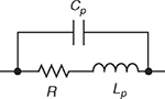
In AC circuits, electrical impedance is the measure of the opposition that a circuit presents to the passage of a current when a voltage is applied. Since the parasitic capacitance is connected in parallel to the resistor (the capacitance shunts the resistor), the complex impedance for such a resistor is given by the parallel connection formula:
$$Z = \frac{Z_R · jX_C}{Z_R + jX_C}$$
Where Z is the complex impedance, R is the resistance, X is the reactance of a circuit, and j is the imaginary unit. In this article, it will be assumed that the parasitic reactance of a real resistor is purely capacitive, so the reactance is:
$$X_C = - \frac{1}{\omega C}$$
So the complex impedance of a resistor with purely capacitive parasitic effects is:
$$Z = \frac{-R · j \frac{1}{\omega C}}{R - j \frac{1}{\omega C}}$$
where ω is the angular frequency and C is the resistor’s parasitic capacitance.
For DC or low frequency applications, we are typically only concerned with the magnitude of this complex impedance. The magnitude of the impedance can be calculated using the following equation:
$$|Z| = \frac{1}{\sqrt{ ( \frac{1}{R})^2 + (2 \pi fC)^2}}$$
where,
R = resistance in ohms
f = frequency in hertz
C = capacitance in farads.
When the above equation is further analyzed, it can be seen that the total impedance of a resistor with capacitive parasitic effects decreases as the voltage frequency increases. This decrease is usually negligible, but in some applications may become quite significant.
As mentioned before, manufacturers rarely make available the typical capacitance values for their resistors. As a general rule, SMD (surface-mounted) resistors have much lower parasitics than through-hole resistors. The explanation lies in the fact that even the lead conductors have a certain ability to store charge. Metal leads that connect the resistor to the rest of the circuit are an example of such conductors. The longer the leads, the more charge that can be stored and the higher the parasitic capacitance. So, the shorter the leads, the less parasitic effects can be seen in a given resistor, which is why SMD resistors have less parasitic effects.
If low capacitance is desired, the resistor should be kept as small and compact as possible. Wirewound resistors should be avoided because the windings generate inter-coil capacitance, which makes them unusable above 50 kHz. Carbon type resistors are usable up to around 1 MHz. Foil resistors, on the other hand, have superior characteristics for high-frequency use, with the capacitance usually less than 0.05 pF, which allows them to function well with frequencies up to 100 MHz.
Parasitic effects are most prominent at high frequencies. For example, a metal foil 1.0 kΩ resistor with 0.05 pF capacitance at 100 MHz would, in fact, behave as a 0.9995 kΩ resistor, when all parasitic effects are considered. This is an example of a good frequency response for a resistor.
For comparison, a wirewound resistor is only usable up to 50 kHz, because of both inductive and capacitive parasitic effects. Even when bifilar (non-inductive) winding methods are used, the inter-coil capacitance limits the maximum usable frequency.
Some applications that are particularly sensitive to parasitic effects are: high-frequency amplifier circuits, GHz clock generators, and microwave circuits.
An example of a circuit that takes advantage of the capacitive parasitic effect is the snubber resistor, used to protect switching elements (switches and thyristors) from voltage spikes which are generated by inductive loads such as electric motors during current cut-off. These are most often made as bifilar wirewound resistors to reduce the inductance. For snubber applications, the resistors are designed so that the capacitance is in series with the resistor, not in parallel as is the case with standard parasitic capacitance.