- Network Sites:
-
 EEPower Day is a free 1-day virtual conference. Learn More
 Potentiometer taper is the relation between the position of the sliding contact and the resistance of a pot. In the majority of variable resistors available this is a linear relationship, meaning that the relative position is equal to the resistance ratio. For example, when the sliding contact is at the middle position, the variable resistance value is half of the full-scale resistance of the potentiometer. For some applications and especially audio volume control, non-linear logarithmic tapers are used.
Taper is the relation between the position of the potentiometer sliding contact and the resistance ratio.
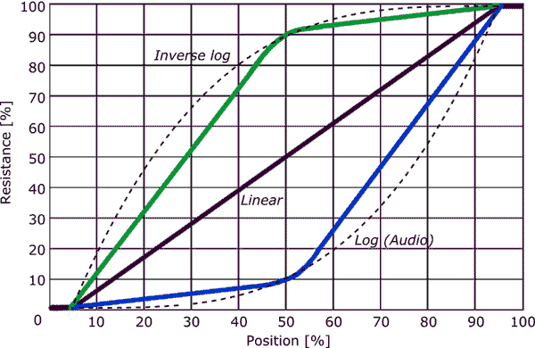
The graph below shows relationship between the variable resistance and the contact position for the three most commonly used tapers: linear, logarithmic (audio), and inverse logarithmic. The simple linear taper is the most common form. The response of the linear taper is linear between 5 and 95% of the contact range of motion. This region where the electrical resistance changes is called the electrical travel. The first and last few percents of contact travel are often only mechanical with no change in resistance. As such, these operating regions are denoted as mechanical travel. The available travel for rotary pots is often denoted in degrees. A mechanical travel of 300° combined with a electrical travel of 270° is common.
The most used non-linear taper is the logarithmic (log) or audio taper. This is mainly used for audio volume control to obtain a more natural, "linear" perception in sound intensity change when you adjust the volume. Because the human ear is sensitive to sound intensity in a logarithmic fashion, at low sound intensities a small change in intensity is perceived as a big change in volume, while at high intensities a large change is required for the same change in perceived volume. To compensate for the ears logarithmic behavior, audio taper pots were developed. While it is called logarithmic, it is actually an exponential curve (the opposite of the logarithmic behavior of the human ear). Sometimes inverse logarithmic (anti-log) pots are used, for example in audio controls which turn counterclockwise, but also in some other specialized applications.
The dashed lines in the graph below show the "real" logarithmic and inverse log curves. In practice, logarithmic types which are used for audio applications do not provide a true exponential response, but follow the curve stepwise. The blue line shows the actual taper curve of an audio potentiometer. This approximation is done because it simplifies the manufacturing process. Instead of a continuously varying resistance track, two different tracks are used which overlap at the middle position. As audio volume control is a non-critical operation in general, this satisfies for these applications. Tapered potentiometers with real exponential curves are available for specialized applications.

Tapered potentiometers are marked with an additional letter, either as a prefix or suffix. The table below lists some common marking codes. Unfortunately there are several different methods of marking. These codes have some overlap and can, therefore, be confusing. The most common marking method is the Asian method which uses B for linear taper and A for audio taper.
| Taper | String | Asia (common) | Europe | America | Vishay |
| Linear | LIN | B | A | B | A |
| Log / Audio | LOG | A | C | A | L |
| Anti-log | - | - | F | C | F |
Books
Online
Link to “The secret life of pots” uses https, but the site is http, so change the link to http to get to the site. Great site!
http://www.geofex.com/article_folders/potsecrets/potscret.htm