- Network Sites:
-
 EEPower Day is a free 1-day virtual conference. Learn More
Resistors are produced with a wide variety of materials and manufacturing processes. Each resistor material has its typical properties and specific areas of use. The main types that are used in electrical engineering are summarized below.
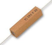 These types are typically made by winding resistive wire in a spiral around a non-conductive core. The resistive wire is usually a nickel-chromium alloy, and the core is often ceramic or fiberglass. A coating such as vitreous enamel is used for protection. The spiral winding has capacitive and inductive effects that makes it not suitable for applications higher than 50 kHz. Often other winding techniques are used to reduce the undesired high frequency effects. Wirewound resistors are often produced for high precision or high power applications. They have low noise, are robust, and are temperature stable. Resistance values are available from 0.1 up to 100 kΩ, with accuracies between 0.001 and 20%.
 The resistive element is made from a mixture of fine carbon particles and a non-conductive ceramic material. The substance is pressed into a cylindrical shape and baked. The resistance value depends on the dimensions of the body and the ratio between carbon and ceramic material. More carbon means a lower resistance. Carbon composition resistors are remarkably reliable, but have a poor accuracy with a maximum tolerance around 5%. Until the 1960s, they were the standard for general applications. They quickly lost market share as other resistor types came on the market with better properties for tolerance, voltage coefficient, temperature coefficient, stability and finally cost. However, their ability to withstand high energy pulses and their high reliability makes them still useful for certain applications. Examples are power supplies and welding controls.
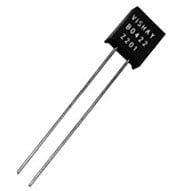
 Carbon Film
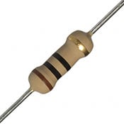
A thin, pure carbon film is deposited on an insulating cylindrical core. A spiral cut is made in the film to increase the resistive path. This increases the resistance value and is also a way to control the resistance value more precise. Values from 1 Ω up to 10 MΩ are available. The accuracy is a significant improvement compared to carbon composition, but metal and metal oxide film have overall better properties and gained therefore more popularity. In applications that require high pulse stability, special carbon film resistors are used.

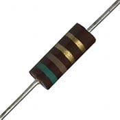
Metal film resistors are usually made of Nichrome, but also other materials such as tantalum nitride is used. The resistive film is printed on a cylindrical or flat insulating substrate. The resistive material is a combination of a Ceramic material and a Metal, and therefore these resistors are also referred to as Cermet. Just as with carbon film, the resistance value is adjusted by cutting a spiral pattern in the film. This can be done with an abrasive or a laser. The stability, temperature coefficient and tolerance are better than for carbon film. Typical tolerances are between 0.5% and 2% with a temperature coefficient between 50 and 100 ppm/K. Stability is lower than for wirewound, but the high frequency properties are better.
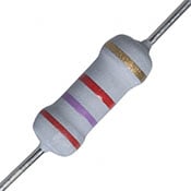
They are similar to metal film with the difference that the resistive material is a metal oxide, such as tin oxide. These durable resistors feature a better reliability and stability than metal film resistors. Furthermore the operating temperature is higher. Therefore they are more used in applications requiring a high endurance.
The foil resistor was invented in the 1960s and is still the most accurate and stable type today. The resistive element is a thin bulk metal foil that is cemented on a ceramic substrate. The foil thickness is several micrometers. Inherent to the mechanical design, they feature a very low temperature coefficient of resistance. They are used for applications with high precision requirements.
The key performance indicators for each resistor material are summarized in the table below.
| Characteristic | Carbon Composition | Carbon film | Thick Metal Film | Metal Film | Precision Metal Film |
| Temp. range °C | -40 +105 | .55 +155 | -55 +130 | -55 +125 | -55 +155 |
| Max. temp. coeff. | 1200 | 250-1000 | 100 | 100 | 15 |
| Vmax | 350-500 | 350-500 | 250 | 200-350 | 200 |
| Noise (μV per volt of applied DC) | 4 (100K) | 4 (100K) | 0.1 | 0.5 | 0.1 |
| R Insul. | 10000 | 10000 | 10000 | 10000 | 10000 |
| Solder (change % in resistance value) | 2% | 0.5% | 0.15% | 0.2% | 0.02% |
| Damp heat (change % in resistance value) | 15% | 3.5% | 1% | 0.5% | 0.5% |
| Shelf life (change & in resistance value) | 5% | 2% | 0.1% | 0.1% | 0.002% |
| Full Rating (2000 h at 70°C) | 10% | 4% | 1% | 1% | 0.03% |