- Network Sites:
-
 EEPower Day is a free 1-day virtual conference. Learn More
 Gustav Robert Kirchhoff
Kirchhoff's laws are essential for resistor network theory. They were formulated by the German scientist Gustav Kirchhoff in 1845. The laws describe the conservation of energy and charge in electrical networks. They are also called Kirchhoff’s circuit laws. Kirchhoff also contributed to other fields of science, therefore the generic term Kirchhoff law can have different meanings. Both circuit laws, Kirchhoff's Current Law (KCL) and Kirchhoff's Voltage Law (KVL), will be explained in detail.
Kirchhoff's Current Law (KCL) states that the sum of all currents leaving a node in any electrical network is always equal to zero. It is based on the principle of conservation of electric charge. The law is also referred to as Kirchhoff’s first law. In formula form this is given by:
$$\sum\limits_{i=1}^n I_i = 0 $$
KCL is easier to understand with an example. Look in the figure at an arbitrary node A from a resistor network. Three branches are connected to this node. Two of the currents are known: I1 is 2 A and I2 is 4 A.
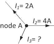
The current law states that the sum of I1, I2 and I3 must be zero:
$$I_1 + I_2 + I_3 = 0$$
$$I_3 = - I_1 - I_2 $$
$$I_3 = -2 - 4 = -6 A$$
The second law is also called Kirchhoff’s voltage law (KVL). It states that the sum of the voltage rises and voltage drops over all elements in a closed loop is equal to zero. In formula form:
$$\sum\limits_{i=1}^n V_i = 0 $$
Let’s take an example to explain the second law. Consider a part of a resistor network with an internal closed loop, as shown in the picture below. We want to know the voltage drop between nodes B and C (VBC). The sum of voltage drops in the loop ABCD must be zero, so we can write:
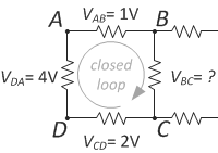
$$V_{ab} + V_{bc} + V_{cd} + V_{da} = 0$$
$$V_{bc} = -V_{ab} - V_{cd} - V_{da} $$
$$V_{bc} = -1 - 2 - 4 = -7 V$$
Kirchhoff's laws form the basis of network theory. Combined with Ohm’s law and the equations for resistors in series and parallel, more complex networks can be solved. Several examples of resistor circuits are given to illustrate how Kirchhoff's laws can be used.
Bridge circuits are a very common tool in electronics. They are used in measurements, transducers and switching circuits. Consider the bridge circuit below. In this example, we will show how to use Kirchhoff’s laws to determine the cross current I5. The circuit has four bridge sections with resistors R1 – R4. There is one cross bridge connection with resistor R5. The bridge is subject to a constant voltage V and current I.
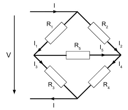
The first Kirchhoff law (KCL) states that the sum of all currents in one node is zero. This results in:
$$I = I_1 + I_2$$
$$I = I_3 + I_4$$
$$I_1 = I_3 + I_5$$
The second Kirchhoff law (KVL) states the sum of all voltages across all elements in a loop is zero. This leads to:
$$R_1I_1 + R_3I_3 - V = 0$$
$$R_1I_1 + R_5I_5 - R_2I_2 = 0$$
$$R_3I_3 - R_4I_4 - R_5I_5 = 0$$
The six sets of equations above can be rewritten using normal algebra to find the expression for I5 (the current in the cross branch):
$$I_5 = \frac{V(R_2R_3 - R_1R_4)}{R_5(R_1+R_3)(R_2+R_4) + R_1R_3(R_2+R_4) + R_2R_4(R_1+R_3)}$$
The equation shows that for the bridge to be balanced with a bridge current equal to zero:
$$R_2R_3 = R_1R_4$$
Example 2: the star-delta (or wye-delta) conversion
Kirchhoff’s laws can be used to convert a star (also called a wye) connection to a delta connection. This is often done to solve complex networks. A widely used application for star delta connections is to limit the starting current of electric motors. The high starting current causes high voltage drops in the power system. As a solution, the motor windings are connected in the star configuration during starting and then change to the delta connection.

The star connection as shown in the figure above, has the same voltage drops and currents as the delta connection shown on the right side, only when the following equations are valid:
$$R1 = \frac{R_{31}R_{12}}{R_{12} + R_{23} + R_{31}}$$
$$R_{12} = R_1 + R_2 + \frac{R_1R_2}{R3}$$
$$R2 = \frac{R_{12}R_{23}}{R_{12} + R_{23} + R_{31}}$$
$$R_{23} = R_2 + R_3 + \frac{R_2R_3}{R1}$$
$$R3 = \frac{R_{23}R_{31}}{R_{12} + R_{23} + R_{31}}$$
$$R_{31} = R_3 + R_1 + \frac{R_3R_1}{R2}$$