- Network Sites:
-
 EEPower Day is a free 1-day virtual conference. Learn More
Inductance is an electrical property of conductors by which an electrical current passing through the conductor induces an electromotive force in the conductor itself (self-inductance) and other conductors nearby. Since resistors are made of conductive materials, they, too, exhibit inductance as an unwanted, parasitic effect. This effect is especially noticeable if the resistor is made out of wire formed into a coil shape. Depending on the application, resistor inductance might be easily disregarded, especially in DC circuits. However, parasitic resistor inductance can be a significant factor in high-frequency AC applications. The reason for this is that the impedance of a resistor rises with the applied voltage frequency due to the increase in its reactance.
Electrical loads can be divided into two types: real (or resistive) loads and reactive loads. Real loads are used to convert electrical power into heat. An ideal resistor is a purely resistive load, which means that all the electrical power applied to the resistor is dissipated as heat. On the other hand, reactive loads convert electrical power into a magnetic or electric field and temporarily store it before returning it to the rest of the circuit. Reactive loads can be inductive or capacitive. Inductive loads store energy in the form of a magnetic field, while capacitive loads store energy in the form of an electric field.
The main difference between ideal resistors and ideal inductors is therefore that resistors dissipate electrical power as heat, while inductors turn electrical power into a magnetic field. Ideal resistors have zero reactance and as a result zero inductance. Unfortunately, electrical devices are not ideal in practice and even the simplest resistors have a slight parasitic inductive reactance.

The B-field of an inductor coil
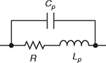
Resistors are used when a purely resistive load is required; so inductance is often an unwanted side-effect, and, in this context, it is called “parasitic inductance". All real resistors exhibit parasitic inductance to a greater or lesser extent, depending on the design and construction of the resistor. Parasitic inductance in an AC circuit can cause unwanted couplings between system blocks or can be the cause of an altered circuit response at high frequencies. The source of inductance problems can be either self-inductance, which exists even when the resistor is far away from other conductors, or mutual inductance, which is observed when other high frequency devices are nearby. Self-inductance may distort the signal at high frequencies, while mutual inductance may introduce noise in the signal path.
Helical wirewound resistors are especially prone to having significant parasitic inductance, because of their coil shape. Resistors designed specifically for use at high frequencies are made of metal film, to avoid creating the coil shape and reduce the parasitic inductance.
In AC circuits, electrical impedance is the measure of the opposition that a circuit presents to the passage of a current when a voltage is applied. It is given by the formula:
$$Z = R + j · X $$
where Z is the impedance, R is the resistance, X is the reactance of a circuit, and j is the imaginary unit. In this article, it will be assumed that the parasitic reactance of a real resistor is purely inductive, and the impedance of such a resistor would be:
$$Z = R + j · \omega · L $$
where ω is the angular frequency and L is the resistor’s parasitic inductance.
As can be seen from the above equations, the impedance of the resistor rises with the voltage frequency increase because the resistor acts as a resistor and inductor in series. This increase is usually negligible, but in some applications is quite significant.
|
Inductance for different resistor types |
|
| Resistor type | Inductance |
| Wirewound | 0.03 – 56 μH |
| Foil | <0.08 μH |
| Metal oxide | 3 – 200 nH |
| Film | <2 nH |
Parasitic inductance usually manifests itself either in resistors with inferior properties such as helical wirewound resistors or in other resistors at very high frequencies. To demonstrate the high frequency problem, let's examine a typical foil resistor of 220 Ω with an inductance of 0.05 μH operating at 1 GHz.
The magnitude of the impedance can be calculated using the following equation:
$$|Z| = \sqrt{R^2 + (\omega · L)^2} $$
Substituting our values we get:
$$|Z| = \sqrt{(220)^2 + (2 · \pi · 0.05E-6)^2} = 383.5 Ω$$
The magnitude of the impedance is 383.5 Ω at 1 GHz, which is an increase of nearly 75% above the nominal DC value. An engineer would not expect this change if parasitic effects were not taken into account. Microwave and RF applications, in general, are particularly sensitive to parasitic effects.
Books
Online